- PRODUCTS
ApplicationFormatApplicationFormatApplicationFeatured


NEWS


News & Events
Solutions to the hold-up time of Ultra-wide Input Range DC-DC Converters
19
Aug
Aug 19, 2022

Introduction and requirements for the rolling stock power system
A typical power converter system of rolling stock is shown as Fig.1. The 15/25 kV energy from the catenary is stepped down by the main transformer to feed the front-end AC-DC main converter and the DC-AC motor inverter for traction motors. The output of the DC to AC auxiliary inverter is 3-phase 380 volts and is used for train lighting, the AC motors of air conditioning fans and the compressors. The 3-phase voltage is also converted to DC by the AC-DC rectifier which can provide current for battery charging. Most electrical equipment used on rolling stock is powered by the onboard battery. It depends on the geographic region and train manufacturer to determine the voltage levels of the on-board battery.

Fig.1 A typical power converter system of rolling stock
The standard voltage levels in a rolling stock system include 24V, 28V, 36V, 48V, 72V, 96V, and 110V.
The most common voltages are 24V, 72V and 110V. Moreover, the electronic device powered directly from batteries without voltage stabilizing device must perform properly within the range of input voltage which is from 0.7 to 1.25 times of the nominal voltage during normal operation. The unit must also withstand the dropped input voltage which is 0.6 times of the nominal voltage for 100ms and the surge voltage which is 1.4 times of the nominal voltage for one second during transient period. As a result, all equipment installed on the rolling stock must be compliant to the requirements.
| Nominal input | 2:1 input range |
4:1 input range |
12:1 input range |
18:1 input range |
Main Region |
| 24V | 16.8-30.0V | 24V (9-36V) |
72V (14-160V) |
72V (8.5-160V) |
Europe |
| 28V | 19.6-35.0V | North America | |||
| 36V | 25.2-45.0V | 48V (18-75V) |
Europe | ||
| 48V | 33.6-60.0V | Europe | |||
| 72V | 50.4-90.0V | 110V (43-160V) |
Europe | ||
| 96V | 67.2-120.0V | Qatar | |||
| 110V | 77-137.5V | China, Europe, India |
Currently, there are a variety of input range of DC-DC converters which are from 2:1 to 18:1 input range and the common voltages in different regions shown in the table above. An 18:1 input range DC-DC converter would cover all common voltages in the railway system. It significantly helps customers to reduce the cost of inventory by simplifying the product combination which is more complicated for 4:1 and 2:1 DC-DC converters.
Speaking of the hold-up time, it ensures the whole system remaining stable even when the input power is cut off to be 0V for a short period of time. According to EN50155 standard, there are three categories for the input Interruption requirements and two categories for the change-over requirements of rolling stock. Please refer to the following table and figure for further explanation.
The requirements of Interruptions of Voltage Supply:
| Class | Requirements |
| S1 | No need to meet any criteria. The unit should perform functionally after the voltage interruption. |
| S2 | Need to meet 10ms hold-up time according to criterion A. |
| S3 | Need to meet 20ms hold-up time according to criterion A. |
The requirements of Voltage Change-Over:
| Class | Requirements |
| C1 | Need to meet 100ms hold-up time at 0.6*nominal voltage according to criterion A. |
| C2 | Need to meet 30ms hold-up time according to criterion B. |

Fig.2 Combination of Interruptions and Change-Over test
Challenge of hold-up time capacitor for ultra-wide input DC-DC converters
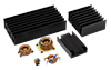
Generally, it needs to add an external capacitor between +Vin and -Vin to extend hold-up time to pass the interruptions and change-over tests. The hold-up time is the period that a DC-DC converter could remain the level of the output voltage within the range of the rated output voltage after the input voltage is interrupted or lost. To reduce the input inrush current, a suggested external circuit (RCD) is required as below.
|
Fig.3 Conventional method 1 |
Fig.4 Conventional method 2 |


From the application note of EC7BW18, we can see the recommended hold-up capacitance from the following table:

For ultra-wide input DC-DC converters, the size of capacitors will become quite large for the required hold-up time. We take EC7BW18 as the example, the required bus capacitor will be 1100uF/35V if it is in the 24V bus system and 50uF/200V if it is in the 110V system.
Therefore, the bus capacitor 1100uF/200V is supposed to be selected for the 24V ~110V system. Besides that, 22PCS of 50uF/200V connected in parallel could be the alternative. However, in this case, the overall dimension of the capacitors would be too large to achieve the expected target. In order to solve the problem, the power converter manufacturer needs to provide the suggested external circuits for the 24V and the 110V bus systems. Otherwise, it would not be a turnkey total solution to end users.

Fig.6
Turnkey solution for ultra-wide input DC-DC converters
There are two common schemes proposed on rolling stock market to overcome the problem described above and offer a turkey solution.
1. Two-stage configuration
It has a boost converter as the front-end stage and an isolated DC-DC topology as the DC-DC output stage. There is a bus capacitor at the output side of the front-end stage for energy storage to provide a roughly semi-regulated DC bus voltage. The related diagrams are shown below. The current would be discharged from the boosted bus capacitor to the isolated DC-DC topology and the load to achieve the longer hold-up time when the input voltage is interrupted.
However, due to the two stages connected in series, it would cause the cost increase and the decrease of the total efficiency. In addition, the high step-up ratio of boost may make the efficiency drop sharply at low line condition. Moreover, the extra external hold-up circuit (RCD) is a must to prevent startup failure.

2. Single stage with step-down charging configuration
The second method is the single stage converter with a step-down constant current charging circuit. The bus capacitor is charged from the input side when the power is on. Technically, the voltage is set to 25 Volts approx. The bus capacitor would be discharged to the input side via a diode to extend the hold-up time when the input power is interrupted. Please see the diagrams below.

The bus voltage would be clamped to 25V approx. when the input voltage is higher than 25V. It would also follow the input voltage and decrease down when the input voltage is lower than 25V. As a result, it may cause hold-up time failure. The table shows the comparison of the two methods:
| Configuration | Pros | Cons |
| Two-stage | Smaller-size bus cap | Complicated control Higher cost and larger volume Not suitable for low power Lower efficiency at low line |
| Single stage with step-down charging |
Easy control Lower cost and low volume Suit all power range |
Needs larger-size bus cap to avoid the hold-up time failure at low line |
Two-stage vs. Single stage with step-down charging
Conclusion
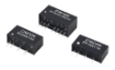
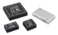
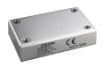
Cincon offers various hold-up time solutions for high-performance and rugged DC-DC converters in the railway and transportation industry. The advantages of ultra-wide input DC converters could be managing inventory easily by simplifying the power product combination, reducing the cost and saving development time by using a single product that supports the various voltage requirements in the rolling stock system. In Cincon product portfolio, the EC7BW18-ECRT/EDRT series would be an ideal example of turnkey solution with the built-in all-in-1 EMI and hold-up time circuitry which helps the power system operate stably.
For more details of railway power, please contact CINCON for more support.
Contact sales@cincon.com.tw for support.
Product page: Ultra-wide input range DC-DC converters